[av_revolutionslider id=’14’ av_uid=’av-6xt6w5′]
- Elimination of quality-robbing boundary-layer mirror seeing
- Elimination of figure-distortion caused by internal temperature gradients, thanks to near to zero CTE of Quartz
- Elimination of focal length change due to thermal expansion thanks to near to zero CTE of Quartz
- Extremely higher self-stiffness of the mirrors
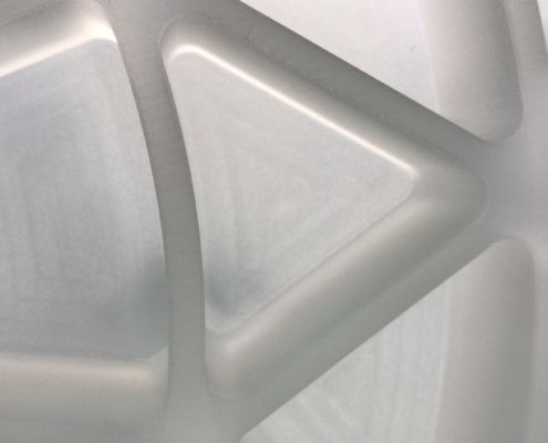
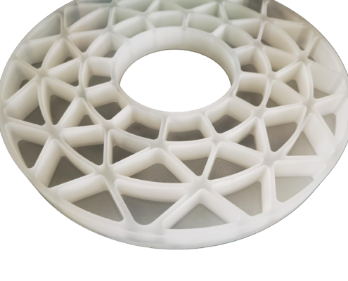
- Maintains tighter alignment tolerances required on modern optical systems through low mass 1/3 to 1/4 the mass of solid mirrors full thickness
- Faster Slews, better tracking performances and higher throughput due to lower inertia of total instrument
- Use of standard mount with lower load capacity with respect same diameter other brand’s telescopes
Mirror seeing
In typical astronomical use a telescope heats up during the day, but is used at night when the temperature is cooler. Optical systems that have properly addressed the thermal issues will outperform those that cannot keep up with changing temperatures. An added benefit of mirrors and systems that are designed to quickly take on the new ambient temperature is that they are typically lighter, which means they can be utilized in larger apertures on smaller craft; air, sea, land & space. They can also slew to object faster.
Commonly used materials for mirrors, such as glass and glass-ceramics, want to hold onto their heat and are poor at conducting it away. These are driven by two distinct thermal properties of a material;
- heat capacity and
- thermal conductivity.
Because most materials cannot take on the changed temperature quickly enough, they radiate in the boundary layer; an extremely sensitive area directly above the optical surface of the mirror. This is equivalent to heat rising off a highway on a hot summer day, except it requires far less temperature delta to cause problems with optics. These performance losses occur long after the visual cues have disappeared. It has a devastating impact on the performance of the optical system. Only when the optic is within a very tight 0.1°C to –0.2°C of ambient temperature will the individual optics themselves not be degrading the system. The best solution to this problem is to correct it at the source, by using less mirror material, which leads to lightweight mirror features that are as thin as feasible. Doing so pulls the dead weight & thermal mass out of the optical system and allows it to perform at optimal levels.
High-level ground-based telescopes try to keep the bulk temperature of their mirrors within 0.1°C to –0.2°C of the ambient temperature, because their empirical data shows a 0.25 arc-second loss in performance for every 0.1°C that the mirror is allowed to go outside this small temperature window. This means a mirror that is warmer by only 0.5°C will degrade the inherent quality of the system by roughly a full arc-second.
It is a fairly large challenge to create some type of sophisticated system that can both measure and cool the mirrors, through forced means, to literally at or below the 0.1°C to –0.2°C of the ambient temperature threshold. Accurately measuring the temperature of an optic to 0.1°C is a challenge in and of itself. Also don’t be fooled by the resolution of a temperature probe. It is not resolution that is needed but real-world accuracy and repeatability.
All mirror materials, including zero-expansion materials, will show optical system quality loss from the boundary layer when the mirrors are not equalized to within the small margin of ambient temperature. The distortion at the boundary layer affects all mirror materials because a zero CTE does nothing to change the thermal mass of the mirror. Just like CTE is a separate property from density. This is why extremely low CTE of Quartz with Lightweight shape of the mirror is absolutely the best solution.
Figure Distortion
Plate glass, borosilicate glass, SiC, aluminum, and any other material that does not have a zero CTE will exhibit a second thermal degradation; figure distortion. This is due to temperature gradients within the bulk of the mirror itself. As ambient temperature drops, the outer portions of the solid or thick-featured semi-lightweight mirror are cooling faster than the internal regions. This causes a distortion of the figure of the mirror. The scale of the problem is based on three main factors;
- The higher the CTE,
- the thicker the material and
- the greater the temperature delta, the larger the figure distortions, which can be different in localized areas of the mirror.
This is in addition to the degradation being caused at the boundary layer. This is the performance reality of using old technologies; especially true for mirrors greater than 400/500 mm. There are very few applications that are not affected by the thermal problems of solid mirrors. Indoor optics labs that experience temperature fluctuations of 5-10°C can be affected by both of these thermal issues.
The thermal properties, and especially the thickness of the material, are some of the main drivers of how nimble a mirror will be; thermal time constant. If we cannot greatly improve the thermal properties of the material, then using less material and substantially thinner features can be a solution, but using a QUARTZ LIGHTWEIGHT MIRROR is the best choice.
Aspect Ratio & Stiffness of Solid Mirrors
A first-order approximation of stiffness is that as diameter doubles, stiffness drops by the square. This means a 2x increase in diameter equals a 4x decrease in stiffness, while maintaining the same aspect ratio. A 150 mm diameter (Ø) mirror that is 25 mm thick (6:1) is considered the 1x stiffness baseline. Then the stiffness of a 300 mm Ø mirror, that is 50 mm thick, is 4x lower than that of the 150 mm baseline mirror. A 450 mm Ø mirror that is 75 mm thick (6:1) will be 9x lower in stiffness than the 150 mm baseline mirror. A 650 mm, 108 thick will be 19x lower in stiffness than the 150 mm.
If we consider 10:1 aspect ratio, a 650 mm Ø mirror that is 65 mm thick, will be 52x lower in stiffness than 150 mm 6:1 (!!)
The general function of a mirror mount is to spread the loads across larger areas and to maintain a given optical surface, as well as alignment tolerances. Often the mirror’s angle and temperature are changing dynamically. All mirror mounts will distort the optical surface, both while temperature is static and also when there is a change in temperature. Scale determines whether these distortions are making a noticeable impact on performance or not. Mirrors can be surprisingly easy to distort.
Large diameter mirrors will use more support points (9, 18, 27, 54, etc.) and in theory have the potential to maintain the same optical surface quality as the 6” baseline mirror that only needs a simple 3-point support. However, more complex mirror mounts, by their very nature, are more prone to errors, including human errors; design and/or implementation errors. As greater and greater numbers of axial support points are used behind the mirror, the mechanics of how that more complex kinematic support is accomplishing the goal are critical. Lateral support, often done at the outer edge, also becomes more difficult and can be a deep topic in an of itself for larger diameter mirrors.
A Quartz lightweigt mirror set up a domino effect for the rest of the opto-mechanical system. The mirror supporting structure does not need to be as heavy, which in turn means the backplates not need to be as heavy, reducing weight of the main instrument structure as well. This reduces the mass carried by the mount and can lead to great performance and/or the use of less expensive mountings; off-the-shelf products for example. Secondary mirrors can show just s much mechanical performance improvement as primary mirror.
How do lower mass mirrors affect the performance of the telescope?
The numerous thermal and optical performance benefits outlined previously benefit the mirror itself. The purpose of the telescope structure is to hold the mirrors a set axial distance from each other, as well as trying to maintain a tight optical alignment tolerance; keeping the optics fixed in 3D space to tight tolerances. Maintaining these two criteria to very small scales is a monumental challenge and makes telescopes deceptively complex.
Mirror mounts alone have the conflicting task of holding the mirrors rigidly, while mechanically distorting the optical surfaces by the smallest amount feasible. This is no easy task. No mirror is “solid” because even full-thickness mirrors are not infinitely stiff. Every mirror mount distorts the optic being support. If you can’t see the distortion, then a more sensitive piece of equipment is needed. Concluded the mirror is not bending is like saying a person vanished after they walked behind an object. Remember, the typical specification calls for errors to be in the double-digit nanometer range. 20nm equals 0.00002mm. It doesn’t take much force to create “large” problems, which is why thermal issues create such large performance losses.
No matter how you look at it, a lightweight mirror that is about 1/3th to 1/4th the mass of a solid mirror will give the system better optical and mechanical performance. It is a domino effect of improvements. If the same mirror mount is used for both a heavy solid mirror and the lightweight mirror,
- the 3-4x lower mass lightweight mirror will bend its support less than the solid mirror,
- the lightweight mirror will have lower lateral support forces and
- compression (piston/focus) of the mirror mount will also be less.
These three factors mean the lightweight mirror will be able to achieve tighter optical alignment and focus tolerances as the telescope moves around the sky. This means the focal plane will maintain tighter spots all-sky.
Even if the same telescope structure is used for both the full-thickness mirrors and the lightweight mirrors, the total telescope mass is obviously reduced for the lightweight mirror telescope. This means it will show improved tracking performance, much higher consistency in dynamic temperature environments and it can potentially slew to the object faster. This means higher throughput for the telescope.

